TX20 Protocol
Thanks to John the Geek who spend the time to fully probe and decode the protocol the TX20 uses, Details of the communication protocol the sensor uses can be found on Johns web site.
https://www.john.geek.nz/2011/07/la-crosse-tx20-anemometer-communication-protocol/
Connecting the TX20
Using the information John provided about the TX20 pins
| Pin | Color | Description |
|---|---|---|
| 1 | Brown | TxD |
| 2 | Red | Vcc |
| 3 | Green | DTR |
| 4 | Yellow | GND |
TxD is connected to pin 11 (GPIO 0 or BCM 17)
DTR is connected to pin 12 (GPIO 1 or BCM 18)
VCC is connected to 3.3V and GND to Ground.
Software
Using some excellent work done already for reading the TX20 on Arduino I used this code as the basis for porting it over to the raspbery pi
http://fabrizio.zellini.org/decoding-la-crosse-tx20-anemometer-with-arduino
The main function calls readTX20 until it gets a good reading, can be straight away but sometimes the checksum failed so this was the best way to always get a good reading.
https://github.com/redstorm1/RPi-TX20
To use different GPIO pins just edit the declarations in the TX20.h file to what ever pins you are using.
#define TX20DATA RPI_GPIO_P1_11 // Input on RPi pin GPIO 11 physical#define TX20DTR RPI_GPIO_P1_12 // Input on RPi pin GPIO 12 physical
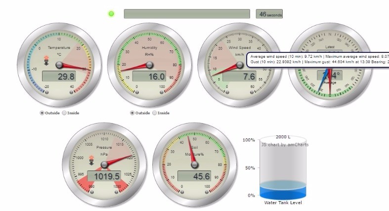
The data from the sensor is stored into a mysql database, this is then used to provide a feed to live gauges on a web page and eventually graphs of wind history.

Live Gauges
http://dev.geektech.co.nz/weather.php